Predicting Signal Behaviour In Opto-Electronic Circuits
OptiSPICE is the only SPICE software available for Opto-Electronics. It incorporates equations governing optical components directly into an electrical simulation framework, thus forming a single-engine optoelectronic simulation tool. Previously, the ability for a single software package to tightly model optical-electrical integration, thermal coupling, and various optical effects (such as interference, reflection, and multiple carrier frequencies) was non-existant.
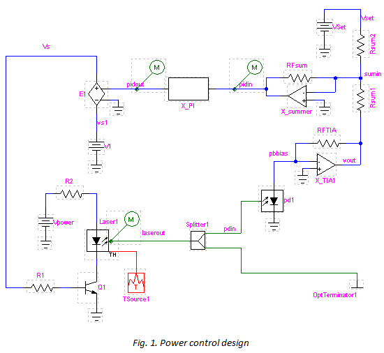
The figure below illustrates a circuit design using a feedback loop to maintain a constant optical power in the presence of temperature variation.
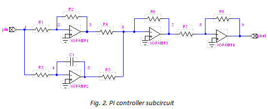
A small percentage of the optical power is split off from the output of the laser and is fed to a photodetector. The output from this detector is used as the input to a closed loop PI controller (see Figure 2). For any small variation in the photodetector current, in response to a small variation of the laser output power (ex. due to temperature change), the PI controller adjusts the bias voltage so that the current through the laser remains constant. As a result, the output optical power is kept constant.
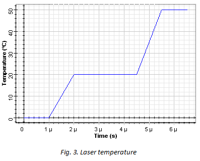
In this design ambient temperature of the laser is varied with time as shown in Figure 3. This temperature variance is fed to the laser through an external thermal source.
Results
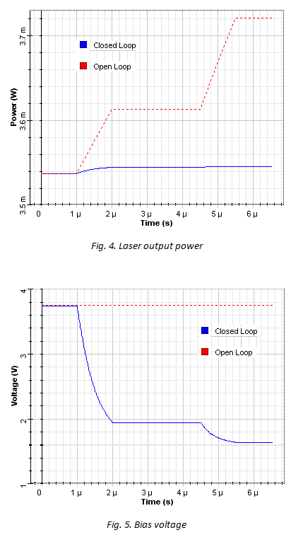
The response of the laser output power is shown in Fig. 4. Responses for two cases are shown – closed and open loop cases. As expected, closing the PI feedback loop causes the laser bias to be adjusted to compensate for the temperature changes.
Fig. 5 shows the bias voltage for the closed and open loop cases. It can be observed from the plot that bias voltage is getting reduced to compensate the increase of temperature in the closed loop case.
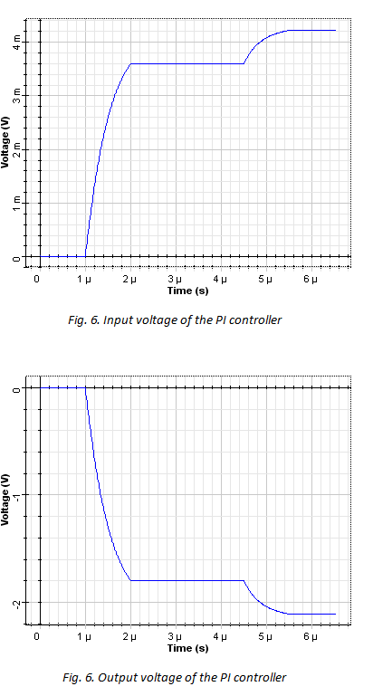
Figs. 6 and 7 show input and output voltage of the PI controller. As it can be seen a very small increase in the input (in the order of mV) causes a significant negative voltage in the output.
Discussion
The power control design must be simulated using a SPICE engine that incorporates both electrical and optical models – OptiSPICE. It cannot be simulated using traditional software packages that rely on co-simulation or equivalent circuit models, as they do not provide sufficient coupling between electrical and optical devices.


