In this tutorial, we demonstrate optical modulation using an electroabsorbtion modulator.
Sample: Electroabsorption Modulator.osch
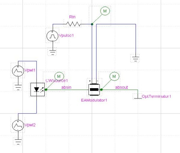
The EA Modulator device is located in the OptoElectric library. It has 2 electrical ports for the bias and RF driving and 2 optical ports as an input and output.
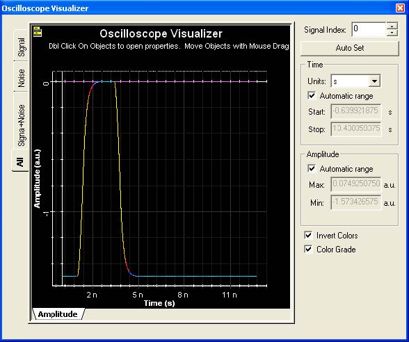
The EA modulator is driven with a voltage source device which is called ‘Vpulse’ and is located in the electrical library . The Vpulse generates a pulse with 2 ns duration, 0.4 ns rise and fall time from -1.5 to 0 V. The other electrical input of the EA modulator is grounded.
The optical input to the EA modulator is from a CW laser device located in the OptoElectronic library and is called ‘CWSource’. The wavelength of the laser is set to 193.1 THz. The CWSource has 2 electrical ports for driving and 1 optical output. The laser is driven with 2 voltage sources called ‘Vpwl’ located in the electrical library. Vpwl is a voltage source that generates piece-wise linear waveform in transient analysis. The values for this voltage source is entered in as a series of time-voltage pair (Ti,Vi) separated by space.Figure 1 shows the layout for this experiment.
Figure 1: Layout of EA Modulator
In order to visualize the signals, we need to place probes on the desired ports. Probes are located in the Probe library. In this example, we put probes on the laser output, on the EA Modulator output and on the electrical input of the EA modulator.
Analysis:
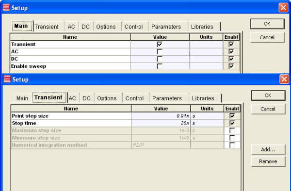
After saving the project, in the Analysis tab, choose Setup. In this example we do Transient analysis for 20 ns with 0.01 ns step size. Figure 2 shows the setup.
Figure 2: Analysis setup of EA Modulator
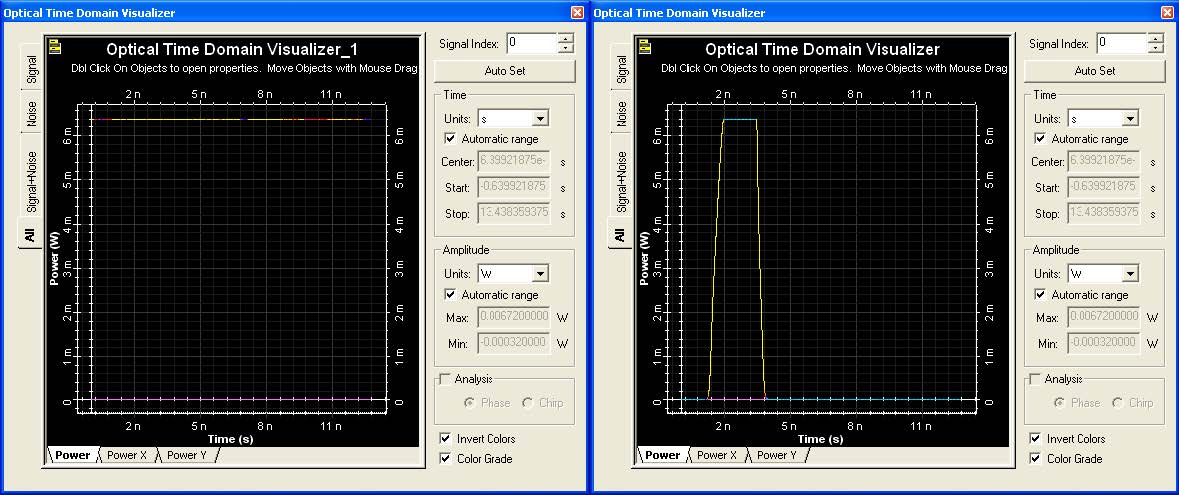
In order to visualize the signal on the probes, first we run the Analysis, then we open OptiSystem to use the visualizers. Following figure shows the electrical drive signal, input to the EA modualtor, and in Figure 4 is the CW source signal and EA modulator output after modulation.
Figure 3: Electrical diriving signal of EA Modulator
Figure 4: CW signal and EA Modulator output


