In this example, we will show you how to simulate optical fiber that has a triangular
with annular ring profile. In addition, we will show you how to optimize given fiber
profile to have zero dispersion at 1550 nm by the powerful parameter scan routines
of OptiFiber.
You can find this example as the DSF.fcd file in the Samples directory.
Defining fiber profile
To define a fiber profile, follow these steps:
| Step | Action |
| 1 | From the “File” menu click “New” to open a new project. |
| 2 | Click the Fiber Profile icon in the “Navigator” pane. |
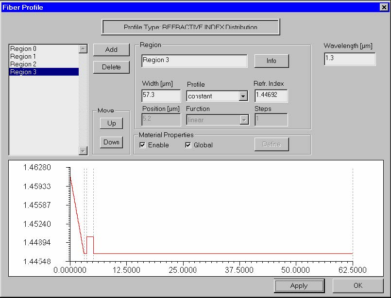
| 3 | In the Fiber Profile dialog box, add four regions: “Region 0” through “Region 3”For “Region 0”, enter the following data: Width: 3.1 Profile: function Function: linear Refr. Index: Define: Start = 1.4615, End = 1.44692 Steps: 100 Click ApplyFor “Region 1”, enter the following data: Width: 0.6 Profile: constant Index: 1.44692 Click ApplyFor “Region 2”, enter the following data: Width: 1.5 Profile: constant Index: 1.45 Click ApplyFor “Region 3”, enter the following data: Width: 57. Profile: constant Index: 1. 44692 Click ApplyEnter the wavelength value 1.3 microns. Your fiber should look like the one below: |
| 4 | Click “OK” to close the “Fiber profile” dialog box. |
Finding the zero dispersion wavelength
To find the zero dispersion wavelength, follow these steps:
| Step | Action |
| 1 | Click the “Modes” icon in the “Navigator” pane |
| 2 | Select the “LP Modes (Matrix Method)” option |
| 3 | Press “Recalculate ”. The program provides the modal index at the given wavelength and shows a preview of the modal field. |
| 4 | Click “OK” to leave the “Modes” dialog box. |
| 5 | Click the “Scan Fundamental Mode” icon in the “Navigator” pane. |
| 6 | In the “Properties of Fundamental Mode” dialog box, click “Calculate” to scan “Wavelength” from 1.4 to 1.6 in 50 steps. |
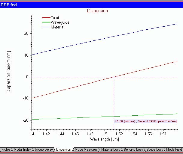
| 7 | Go to “Dispersion” view tab. The zero dispersion wavelength is located in the vicinity of 1513 nm. |
Your “Dispersion” view tab should look like this:
Optimizing profile for a required zero dispersion wavelength
Now, we can use the powerful capability of OptiFiber to scan over our design
parameters. Let’s define, as a design goal, to achieve zero dispersion at a certain
wavelength, say 1550 nm. As we will see, we can accomplish that by changing, for
example, the distance between the triangular core and the annular ring, i.e. the width
of “Region 1”.
When we find the optimal width we can use it to calculate the global dispersion
characteristics vs. wavelength.
| Step | Action |
| 1 | Now, go back to the “Properties of Fundamental Mode” dialog box by selecting “Scan Fundamental Mode” in the “Navigator” pane. |
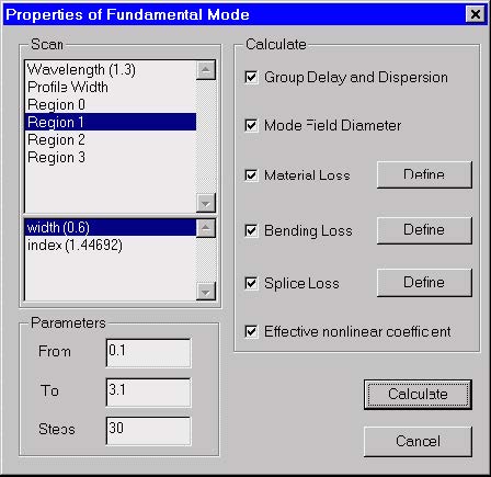
| 2 | In the “Properties of Fundamental Mode” dialog box, select “Region 1” from the “Scan” upper list, then select “Width” from the “Scan” lower list. |
| 3 | In the “Parameters” section, enter the following values: From 0.1, To 3.1, Steps 30. |
| 4 | Click “Calculate”. |
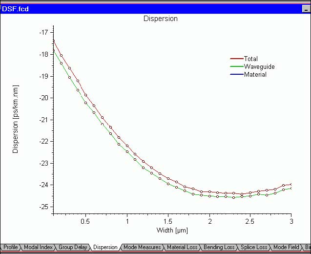
| 5 | Go to “Dispersion” view tab. The dispersion vs. the width of the intermediate layer is shown there: |
| 6 | 6. From the previous dispersion vs. wavelength picture we know that we need ~ 3 [ps/nm/km] reduction of the total dispersion at 1550 nm. With the left mouse button, click-and-drag over the “Total dispersion” curve to find the point, whose dispersion is 3 [ps/nm/km] less than the dispersion, corresponding to the current width of 0.6 ìm. One can see that the 3 [ps/nm/km] reduction falls between the widths of 1.3 and 1.4 ìm. |
| 7 | Go back to the “Fiber Profile”, select “Region 1”, and change its width to 1.32 ìm. |
| 8 | Go to the “Properties of Fundamental Mode” dialog box and scan over the wavelength from 1.4 to 1.6 ìm in 50 steps. |
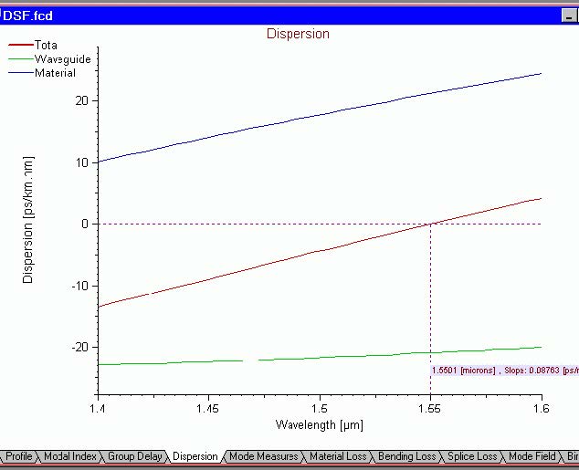
| 9 | Go to “Dispersion” view tab. The zero dispersion wavelength is 1550 nm. |
You just optimized the fiber design to obtain the zero-dispersion wavelength close to
1.55 microns.
Your “Dispersion” view tab should look like this:


