There are two ways to perform the parameter sweep simulation with OptiFDTD:
• Simulation Using Script. This method asks the user to edit the VBscript code to sweep the layout parameters. The user can use the internal VB function to access the power spectrum.
• Simulation Using automated Sweep. With this method, OptiFDTD provides a graphical user interface to define the swept parameters, iterations and a parameter sweep viewer to observe all the results (power in the center wavelength, transmission spectrum and reflection spectrum) for all the swept parameters.
Simulation Using Sweep mode can be transformed to Simulation Using Script mode, i.e. a VB script code can be automatically generated after the sweep parameters are defined in the parameter sweep interface. For users who want to use these VB functions, please check the corresponding reference and the automatically generated VB code.
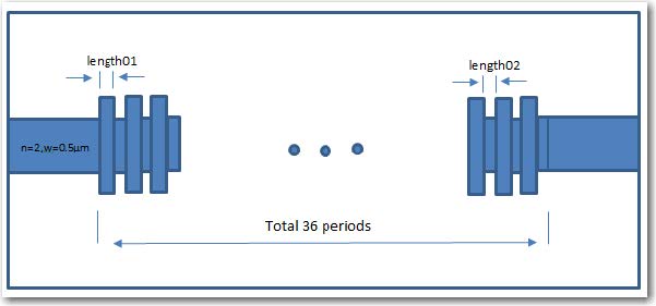
In this lesson, we will discuss how to use Simulation Using Sweep and the corresponding results viewer. A simple 2D grating layout will be used to demonstrate the steps. Figure 1 is a layout sketch. The layout contains input/output waveguides and 36-period grating. Both waveguides use the same material with a refractive index of n=3.3. Each grating unit cell contains two waveguides: the first has a width of 0.7µm and a variable length of “length01”, the width of the second waveguide is 0.5 µm with a variable length of “length02”. We will try to scan the two parameters “length01” and “length02” in the simulation. The sample layout can be found in the 64bit sample folder, titled “x64_sample63_2DTM_2LevelParamterSweep.fdt”. folder, titled “x64_sample63_2DTM_2LevelParamterSweep.fdt”.


