Calculating θwg for tilted waveguides
When the output waveguides are tilted, the phase becomes a sloped straight line. In You must be careful which point you use to calculate θwg . You must know exactly which point was used to make the information consistent with definitions used in the OptiSystem calculation.
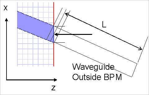
Figure 32 illustrates a tilted waveguide. The BPM zone is connected to an external waveguide outside. The other waveguide is characterized by another separate BPM calculation, or (in the case of a straight isolated waveguide) by a user-supplied manual calculation. The length of the external waveguide depends on the reference point used in the definition. The reference point is the place where the optical phase is taken from.
Figure 32: Define the length of the waveguide outside the BPM zone
It doesn’t matter which of the three possible lengths shown is used, provided that the length definition and the optical phase point are taken from the same place.
To avoid confusion, we recommend the following rules, broken down case by case.
2D Calculation
For 2D calculations, use the mesh point closest to the centre of the waveguide where it intersects the end of the calculation.
3D Channel
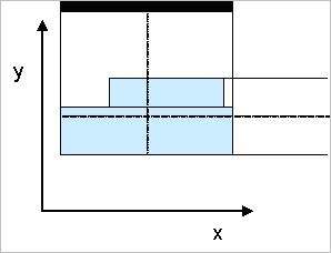
For the 3D Channel waveguide, the view from the layout in the x-z plane defines the width of the entire channel. Use the midpoint of the channel in the x-z plane to define the x coordinate of the optical phase point. This makes the definition consistent with the 2D definition (see Figure 33).
Figure 33: Midpoints for 3D Channel
The channel consists of layers at a certain depth. Use the midpoints at the top of the uppermost layer and the bottom of the lowest layer to define the y coordinate of the optical phase point.
3D Fiber
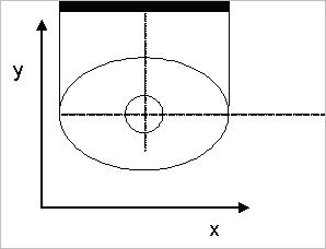
The 3D fiber consists of concentric circular or elliptic layers. Use the common center point of the layers (see Figure 34).
Figure 34: Midpoint for fiber
3D Diffused
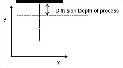
The midpoint in x can be defined the same way as for the other midpoints. A good nominal distance to move below the substrate is the diffusion length for the diffused waveguide under consideration (see Figure 35).
Figure 35: Midpoint for diffused waveguide


