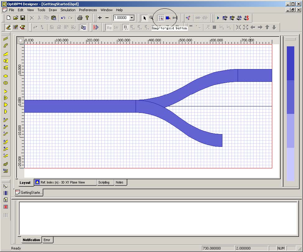
To create a basic project, perform the following procedure.
| Step | Action |
| 1 | On the Tools toolbar, select Snap-to-Grid (see Figure 16). |
| 2 | From the Draw menu, select Linear Waveguide.
The cursor changes into a cross-hair when you move it into the project layout window. |
| 3 | To draw the first waveguide, in the project layout window, click in the left side of the project layout at Origin, drag the waveguide towards the right side of the project layout, and release (see Figure 16).
Note: Click the Select button |
| 4 | To edit the waveguide properties, from the Edit menu, select Properties, or double-click on the waveguide in the layout.
The Linear Waveguide Properties dialog box appears. |
| 5 | Use the steps illustrated above to create a layout similar to the one seen in Figure 16. |
Figure 16: Layout design
| 6 | Click the Ref. Index (n) 3D XY Plane View tab at the bottom of the layout window.
The refractive index view appears. This view shows the refractive index distribution in the transverse (XY) plane at the position Z = 0. If your linear waveguide starts at Origin (see Figure 16), you should see the Channel waveguide we specified in the Profile Designer procedure Defining 2D and 3D channel profiles. Click on the Palette button to see the refractive index scale (see the first button in the toolbar shown in Figure 17). There are many other display options to choose from. Right-click on the layout to see a list of additional features. |
Figure 17: Palette button
You should also become familiar with the Z button found on the Refractive Index View Type toolbar (see Figure 18). Use of this button allows you to move the Z position of the XY plane. You can adjust the Z position until you are satisfied that the refractive index is accurately portrayed in the 3D space. Ensure that you have created the correct shape, as this is the shape that will be passed to the simulator.
Figure 18: Refractive Index View Type toolbar


