
- This topic has 17 replies, 3 voices, and was last updated 8 years, 4 months ago by
 alistu.
-
AuthorPosts
-
-
December 24, 2015 at 7:30 am #28883
 ferasParticipant
hello everybody
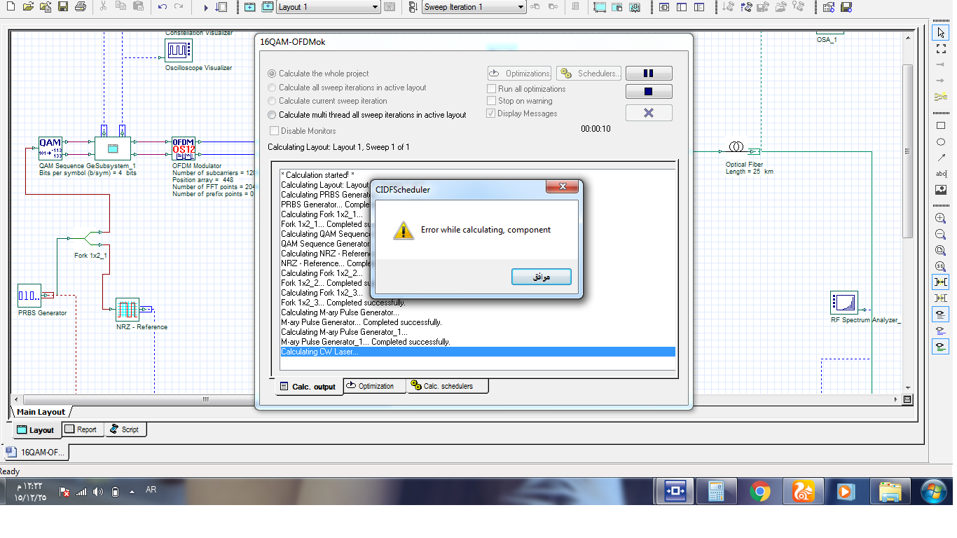
i designed a 16QAM-ofdm system with 1200 ofdm submariner (frequency spacing=15 KHz )so i want to do this a bandwidth=20MHz , but in my simulation i can not do this with a right result , i set the data rate = 80 MHz but the simulation gave me error message
can anybody help me please
how can i set the BW and the bitrate to get 15 KHz frequency spacing.
thank you very muchAttachments:
-
December 24, 2015 at 7:27 pm #28886
 alistuParticipant
Hi Feras,
Can you please upload a screen shot from the error message you mentioned you were receiving while running the simulation? I ran the simulation and it went smoothly without any errors (even though BER analyzer did not show desirable but constellation diagram was not that much corrupted)?
Regards
-
December 25, 2015 at 4:25 am #28892ferasParticipant
-
December 25, 2015 at 2:07 pm #28899alistuParticipant
Hi Feras,
Unfortunately, I cannot figure out why this error is given even though constellation is clear. I tried using BER test set and the same error was achieved.
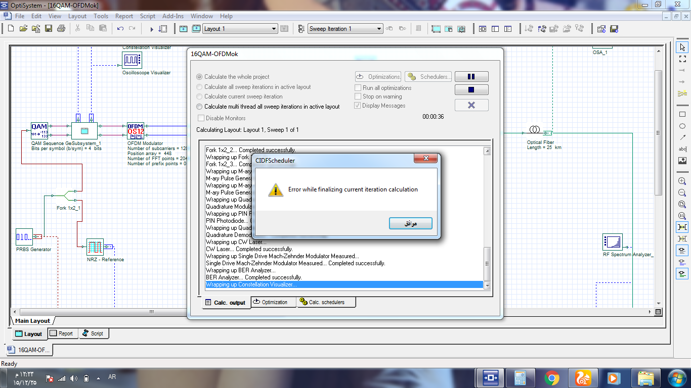
The second error error seems to be due to the memory problem as you have mentioned, but not the first one. Are you using 32-bit version?
-
December 25, 2015 at 2:50 pm #28902ferasParticipant
hi alistu,
yes i am using optisystem13 32bit -
December 25, 2015 at 3:35 pm #28907alistuParticipant
I remember facing the same problem (problem while calculating component) when I used version 13 – 32bit, but then I installed 64 bit version and did not face the problem for the exact same file (whose had a rather large size like yours). So I suggest you do the same. Nevertheless, not always the error can be related to 32-bit version being used.
-
December 25, 2015 at 4:18 pm #28910ferasParticipant
thank you very much alistu , but please i have three more question if you can help me please .
1- why when we run the simulation it still give me BER value , what the BER cause by??
2- what the position array in OFDM component ( modulator/demoudulator ) mean ??
3- what the time window parameter in layout parameters mean??
Regards -
December 25, 2015 at 6:38 pm #28914alistuParticipant
You’re welcome Feras. To better understand position array, I refer you to an explanation by Damian given to me a while ago:
Time window corresponds to the time length of the whole simulation bit sequence. You can calculate time window this way:
time window = (sequence length)/(bit rate)
-
December 26, 2015 at 3:16 am #28918ferasParticipant
hi alistu
tank you very much for your answer it was very helpful ,there is only one question in my head about the BER that i write it in the previous replay
Regards. -
December 26, 2015 at 4:52 pm #28923alistuParticipant
You’re welcome Feras. Unfortunately, I don’t know the reason for the problem you mentioned you have been facing. As I pointed out in my reply #28899, I got the same error using BER test set even though the constellation diagram does not imply such an error being there in the system.
-
December 26, 2015 at 5:05 pm #28924ferasParticipant
hello alistu and thank you very much but i mean the question that i said in it (( 1- why when we run the simulation it still give me BER value , what the BER cause by?? )) , and is not the BER=0.33 is too high or it is normal value in such system
Regards. -
December 26, 2015 at 6:41 pm #28927alistuParticipant
I don’t really know the reason, and I think it is somehow related to the software programming and so on (When I run the program, no error is given and the BER is shown as expected). I hope Optiwave team will analyze this and give you the answer and also confirm if the problem is because of 3-bit version being used, as it seems to be the case.
-
December 27, 2015 at 4:14 am #28928ferasParticipant
hello alistu ,
thank you very much for your helping , i will try to get the answer from optiwave support team .
thank you again .
Regards. -
December 27, 2015 at 2:34 pm #28932alistuParticipant
You’re welcome Feras.
Regards
-
-
-
December 24, 2015 at 10:59 pm #28888
 Mohamed Ben zegalamParticipant
Hi Feras
to be able to set the frequency spacing to 15 KHz, you have to consider and assume other parameters
Fs= spectrum Bandwidth/ #FFT, in your case. you would like to have fs=15KHz, and BW=20MHz so the #FFT will be 1334
also Fs =Bit rate/(M*Nsc), assume bit rate equal to 20Mbps and M=4 (16QAM), so the Nsc will be 133
in addition, you have to change the frequency of the quadrature modulation/demodulation and frequency cut off to MHz instead of GHz and adjust the values according to your design.
-
December 25, 2015 at 2:57 pm #28905Mohamed Ben zegalamParticipant
Hi Feras,
as you know #FFT is the maximum number of the Nsc, so when you set the #FFT to 64 and Nsc to 16. that is mean just 16 of the #FFT will be active or use to transmit the data and the other will be zero, but the spectrum will be consider all #FFT, that is why spectrum BW= Fs*#FFT.
you can try that, for example set the #FFT to 12 and the Nsc 4. then after you run the simulation go to report>>go to the OFDM modulation component>>graphs>>OFDM FFT. you can see the spectrum and all the #FFT point including the Nsc
-
December 25, 2015 at 3:05 pm #28906ferasParticipant
hi mohamed ,
thank you very much for your answer it was very helpful
Regards.
-
-
AuthorPosts
- You must be logged in to reply to this topic.