
- This topic has 23 replies, 3 voices, and was last updated 8 years, 2 months ago by
 alistu.
-
AuthorPosts
-
-
February 12, 2016 at 7:51 am #29630
 marvi groverParticipant
hello everyone!!
i need to know how can we introduce variable attenuation in a single FSO system using optisystem.
can anybody help me with this.
i shall be thankful.Regards
Marvi -
February 12, 2016 at 7:58 am #29646
 alistuParticipant
Hi Marvi,
In order to introduce such a parameter, you can use script mode for the attenuation parameter and then write a formula with some variables. I have explained this in more detail in the following forum topic:
Regards
-
February 13, 2016 at 12:13 am #29672marvi groverParticipant
thankyou so much Alistu.
in that system, the rain rate has been fixed at ‘2’, how can i make this value variable??? for example : the formula i want to implement is attenuation = (3.91/v)(1550/550)^-q , where v is the visibility in kilometers and q is some number. so i will write this formula in th script of attenuation, but i want the values of v and q to be variable, that is they change according to some condition which will be specified in the matlab component that i will be attaching before the FSO channel.
how can i do this??
please suggest me a solutionregards
marvi-
February 13, 2016 at 1:12 am #29675alistuParticipant
You’re welcome Marvi. If I am getting it correctly, you want the attenuation to change with time in the middle of calculations according to parameters defined by Matlab component. I hope you realize it is hard to talk about it when I don’t know anything about the program and so on, but I think the signal is only sent once from Matlab component into the fiber in OptiSystem and attenuation is calculated only once. This should be taken into consideration.
-
February 13, 2016 at 1:48 am #29676marvi groverParticipant
yes alistu, i want the attenuation to change, but yes you are right, it is not possible to change it in the middle of calculation.
but is there some option available where i can specify the global parameter as a “variable” for example visibility as ‘v’, and then relate to a matlab variable, so that if i change the value of ‘v’ in matlab component, then this value of v is used in the formula for attenuation calculationin optisystem.
how do i relate a matlab variable to optisystem “variable”.waiting for your reply
regards
marvi -
February 13, 2016 at 2:57 am #29682alistuParticipant
Unfortunately I don’t know how it is possible to export any parameters from Matlab component to optiSystem where the value of that parameter can be used via script mode for another parameter. However, the attenuation can be entered from a file as you can see in fiber properties. What I am not sure in here is whether the values of the attenuation should only be versus wavelength, or it is possible to use attenuation values versus time in the file. If the second option is possible, maybe something could be done in your case to change attenuation versus time.
-
February 13, 2016 at 8:49 am #29683marvi groverParticipant
ok alistu . thankyou so much for your help.
-
February 13, 2016 at 9:03 am #29685alistuParticipant
You’re welcome.
Regards
-
February 13, 2016 at 9:52 am #29689marvi groverParticipant
hii alistu
i need some more help.
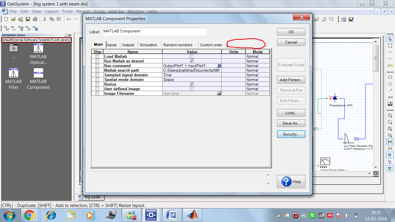
when i am including the matlab component in optisystem , and i click on its properties, i am not getting the ‘ user parameters’ tab in it, which is shown in the tutorial.
i am attaching the screenshot of it. please help me to get itAttachments:
-
February 13, 2016 at 10:32 am #29691alistuParticipant
I cannot see it in my installed OptiSystem version either. And I am using version 13.0.3. The tutorial seems to have been made using an older version of the software, but the parameters can most probably be found in other tabs. Is there any specific parameter that you are looking for?
-
February 14, 2016 at 1:06 am #29696marvi groverParticipant
in the user manual about how to add matlab component ,it is written that the input parameters of the component have to be specified in the matalab component properties. so i think user parameter tab is neccessary to specify the input parameters which i will be using in my matlab code. i am attaching a screenshot.
Attachments:
-
February 14, 2016 at 1:34 am #29698alistuParticipant
In the newer OptiSystem versions, you can add the new parameter in the main tab of the properties window. You can see an “Add Param…” button on the right side of the Matlab component properties window. Using that button you can add your new parameters which all appear under the “main” tab.
-
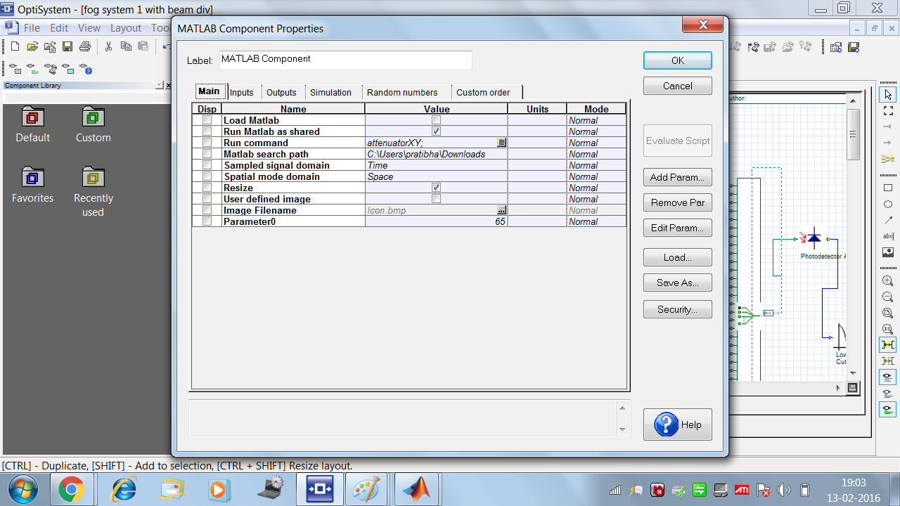
February 14, 2016 at 8:36 am #29700marvi groverParticipant
yes alistu, thankyou so much
i was able to add the parameter but now i am getting error in my matlab code, i am the screenshots.
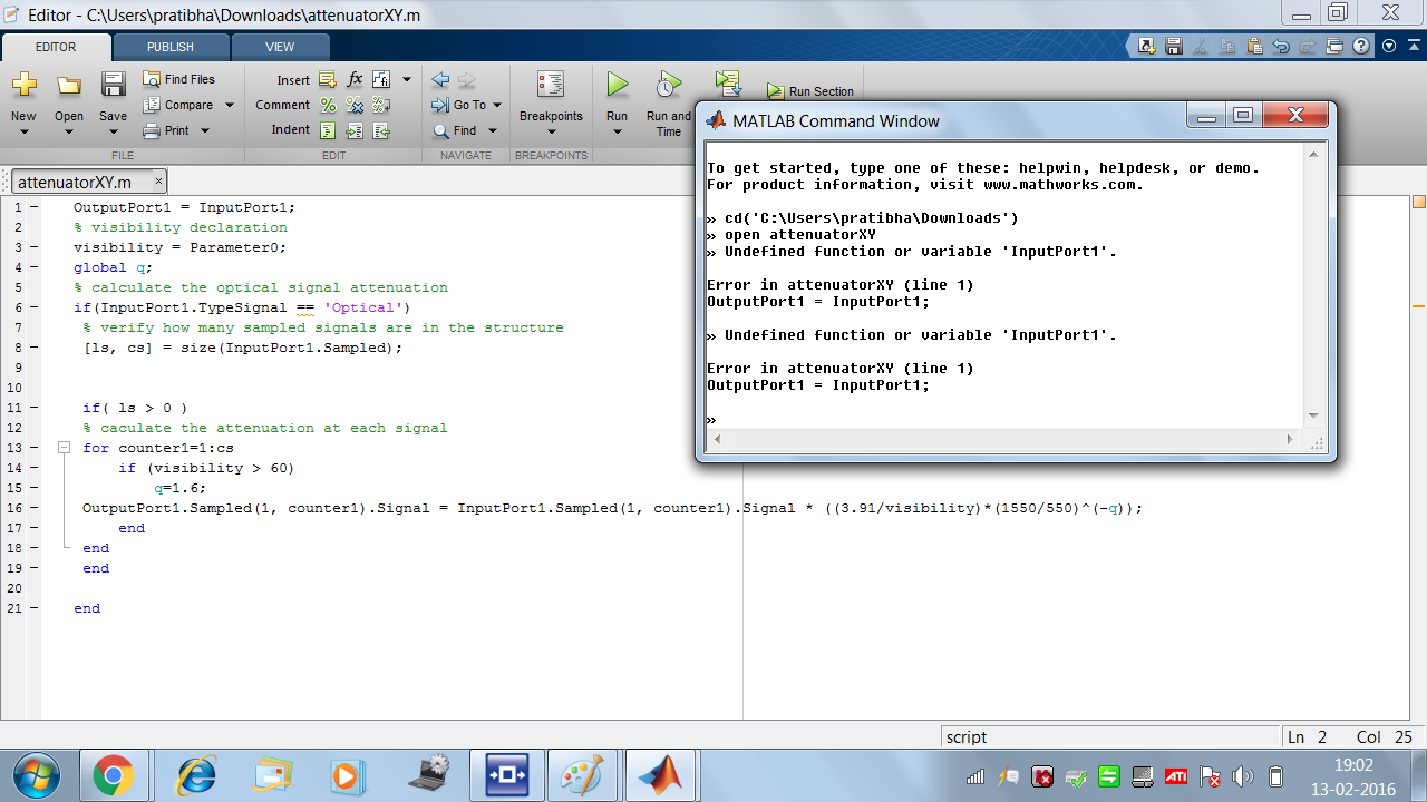
i am getting an error in the first line “outputport1=inputort1”
i read your reply for the same problem in the forum but m nt able to correct it. i am opening the program using tha command windoe only.
please have a look to find out what the prblem is.thankyou
Attachments:
-
February 14, 2016 at 8:41 am #29703marvi groverParticipant
i think i have not used the array editor shown in the tutorial.perhaps that is the reason for this error but i am not able to find the array editor, how to open it ??
it is in matlab or optisystem??? -
February 14, 2016 at 9:22 am #29704alistuParticipant
You’re welcome. If you are using the example from OptiSystem and have given the right address, then I really don’t think there should be any problem. BTW, by putting .osd and .m files in the same folder, you won’t need to address the .m file in .osd Matlab component. Can you please mention the error you are receiving while running the co-simulation?
-
-
-
February 12, 2016 at 12:03 pm #29653
 prakash jatParticipant
hi alistu
can you send me more example file like on dynamic scintillation index ,attenuation ? please-
February 12, 2016 at 1:03 pm #29655alistuParticipant
I don’t have any other examples of attenuation being considered in such a way in OptiSystem, but if you would like to see any other examples, you can introduce a formula and I will show you how to use script mode. BTW, enabling scintillation intensity adds scintillation to the channel by OptiSystem (Index refraction structure can be determined under “enhanced” category).
-
-
February 14, 2016 at 9:25 am #29705alistuParticipant
In order to open array editor, you need to open matlab command window using the option in Matlab component before running the simulation. After running the simulation, type “workspace” in Matlab command window and there, you can choose arrays and functions. This helps better understand what is going on, but is not necessary for the program to run correctly.
-
February 15, 2016 at 11:12 pm #29753marvi groverParticipant
ok Alistu
thanx a lot for your help.
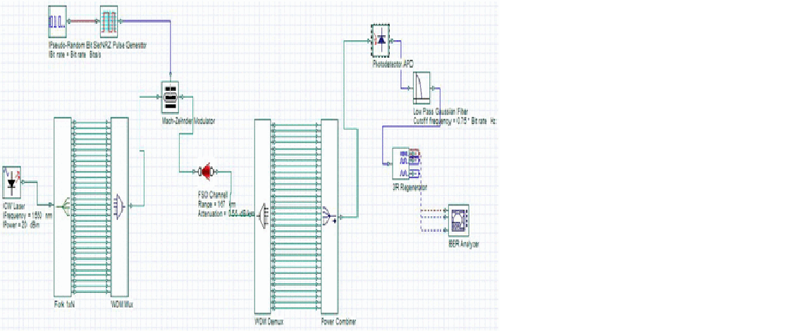
here is a new question i wanted to ask about the component ‘fork’ used in optisystem. what is the exact function of the fork. in the ‘help’ about the fork, it is written that it copies the input to multiple output port, but i have a doubt here, if the fork copies the input to the output, then the power of each signal at the output should be same as the input signal , i am attaching a screenshot of a system, refering to that….how can we give one signal of a particular power at the input and rceive many signals of the same power at the output????
is there some power multiplier or something like that present in the fork.Attachments:
-
February 15, 2016 at 11:49 pm #29755alistuParticipant
You are right about no such component being present in practice. Components that increase power in practice are amplifiers which, of course, add noise to the signal. However, when you want to have several copies of the same signal, you can use it as a tool in OptiSystem. I think I have read the paper whose image you have attached and I believe the use of fork was not correct there.
-
February 16, 2016 at 12:04 am #29756marvi groverParticipant
okk, thankyou Alistu.
actually i have seen ‘fork’ being attached in a lot of systems which have done simulation using optisystem. all of them have used it for the duplication of the input signal, but i think there must be some practical justification to the use of this component which i am not able to find. beacuse ultimately these systems have to be realized practically. CAn we ask Damian Marek about this??, may be he has some more knowledge.
please let me know if u find out out something about this.
i shall be really grateful.Regards
Marvi -
February 16, 2016 at 2:30 am #29763alistuParticipant
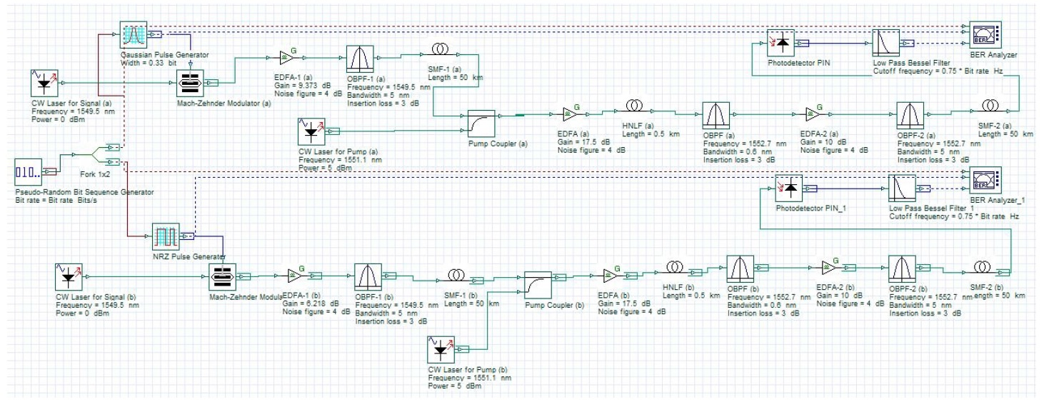
You’re welcome Marvi. Damian can definitely explain this better, but let me give another example: In the system shown in the attached image, you can see two schemes being compared together. Instead of using two PRBS generators, only one is used and then a fork is added. Obviously, such a thing is not implemented in practice, but the use of fork suits the purpose of comparison.
Regards
Attachments:
-
February 16, 2016 at 4:00 am #29772marvi groverParticipant
yes Alistu..
in the system which you have attached, the function of fork is quite justified for the simulation purposes.
thankyou so much for the help.
regards
marvi -
February 16, 2016 at 4:16 am #29773alistuParticipant
You’re welcome Marvi. In other words (in a better eplanation), the use of fork in the attached example is not to duplicate power (or to amplify the signal) in order to get better results in terms of BER and Q-factor. If you have doubts about using fork in any particular case, feel free to ask.
Regards
-
-
-
AuthorPosts
- You must be logged in to reply to this topic.