
- This topic has 13 replies, 3 voices, and was last updated 9 years, 11 months ago by
Damian Marek.
-
AuthorPosts
-
-
May 11, 2014 at 1:17 pm #11437
Abdallah Ismail
ParticipantDear All,
Thanks for this great forum.
I’m working on designing Mode Division Multiplexing (MDM) system,I need to use Matlab Component to design ideal spatial mode multiplixer.
I followed the Applicaion note “Matlab component…Creating a component to handle optical signals” but the file still empty and the workspace is empty.
So i don’t know how to follow the figure 3 in the application note.
Also I need help to know how to get few spatial modes in matlab component and put them on a single port on the the output of the component that will be connected to special design multimode fiber
Best RegardsAttachments:
-
May 12, 2014 at 2:53 pm #11454
Damian Marek
ParticipantHi Abdallah,
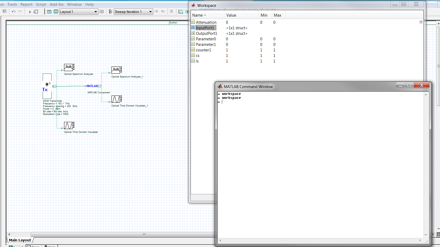
One way to look at the variables that are created in the workspace, is to first enable the parameter “Load Matlab” in the Matlab component. Then after the simulation you can write “workspace” into the Matlab Command Window which will appear.
It is possible to choose and then combine desired modes in a Matlab component by simply deleting parts of the input data structure. However, using OptiSystem’s built-in Mode Selector component may be even simpler. I have attached an example of using the Mode Selector component to capture and combine the 3, 5, 9 and 12 modes of a multimode fiber.
Attachments:
-
May 14, 2014 at 8:14 am #11509Participant
Hi Damian,
I don’t know why the file is not opening,I tried with it using optisystem 10 and optisystem 12 but the same message appear “fail to load the file from the storage”, and sometimes ” violence of sharing….”
If you can help or sending image for the design I’ll be grateful.
Best Regards-
May 14, 2014 at 9:08 am #11512Participant
Hi,
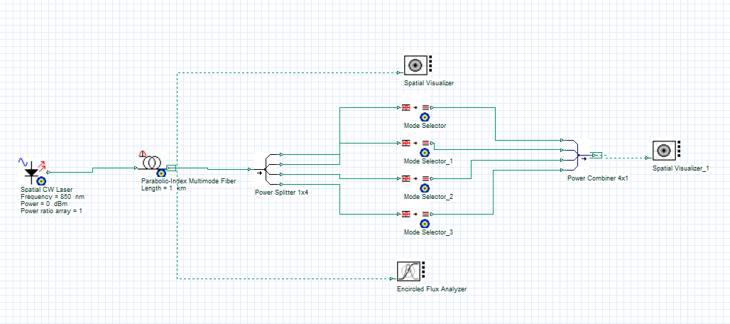
Here is a picture of the layout. It is quite simple actually, the main idea is using the mode selector component to choose just a single mode from the available modes and then combining all of your chosen modes into a single signal.
The Mode Selector can be found in the Default/Receivers Library/Multimode/ folder.
Attachments:
-
May 14, 2014 at 1:38 pm #11518Participant
Hi Damian,
what is the meaning of the number in the mode selector? I know modes like LP01,LP11,LP10,etc but i don’t know the relation with these numbers in mode selector.
your layout inspired me to build mode multiplexer and DE-multiplexer but i found that the power combiner just produce single mode or the fundamental mode,From its equation in the help,i think it is just star coupler with single output and the reverse for the power splitter.
Is this correct?Please check the file i attached for my idea?I may not know how to use mode selector.
your advice is very helpful and enrich my knowledge.
ThanksAttachments:
-
May 15, 2014 at 9:22 am #11548Participant
Hi Abdallah,
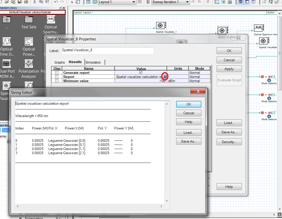
You can look at the modal information (polarization, mode type) by going into the Component Properties of the Spatial Visualizer (right-click, then choose Component Properties). Then look under the Results tab and click on the small icon by the Report parameter. I have attached a snap shot of what it looks like. For your design they are Laguerre-Gaussian modes.
I’m not running into the same problem as you for observing the modes. If you change the mode number in the Spatial Visualizer you should be able to see the four different modes that you combined with the Power Combiner. The only problem I saw was was that your Spatial Visualizers and Mode Selectors were not centered at the correct frequency and no modes were showing. The lasers are centered at 850 nm, so I went into the visualizer and selector parameters and switched the center frequency.
This should fix your layout!
Attachments:
-
May 20, 2014 at 6:59 am #11714Participant
Thanks Damian,
It is working,But did you know how can i generate Linearly polarized modes without using external component.
The generated modes from CW spatial laser is Laguerre-Gaussian or Hermite-Gaussian but i need to use linearly polarized modes.
Also If i used external component as mode converter,did mode selector and spatial visualizer will work with it.Best Regards,
-
May 20, 2014 at 10:04 am #11725Participant
If you connect the Laser source to a optical fiber you will end up with LP modes. The LP modes will depend on the refractive index profile of the fiber. For your second question there should be no problem integrating with the mode select and visualizer, as long as you respect the data structure that is used. Try importing a spatial signal into Matlab and looking at it in the workspace.
-
-
May 13, 2014 at 3:24 am #11456Participant
Thanks Damian for your response,
I followed the instructions carefully,I defined the input and output and the two parameters as technical notes,changed directory, Opened m file, and opened workspace but it was empty.
Does optisystem generate a list of variables in workspace automatically or i define it?
Also I copied the code in the technical note to the m file ,but still the workspace is empty.
I need to know where is the wrong,this is not my actual design,i just follow the instructions in AttenuatorXY example in the technical notes.
can you help me to find the right way?
Regarding the second issue,I’ll follow your guidelines and back to you with the results.
Best regards.-
May 13, 2014 at 9:03 am #11463Participant
I’ll help you out with this problem. If you run OptiSystem with the “Load Matlab” option selected, it should be possible to see the variables created after the simulation is completed. If you open the m-file and then look at the workspace the variables will not be there. You really have to use the Matlab command window that opens up when you run the simulation, so you should not have to open the m-file. Try this and if it does not work please send over the archived OptiSystem file and Matlab file and I’ll see if the problem is somewhere else.
Regards,
Damian-
May 14, 2014 at 8:10 am #11505Participant
Dear Damian,
I really appreciate your support,I attached the two files.
I followed the instructions in the pdf file that I attached in the first post.
The file is running but when i type the workspace command after running ,It is appear empty.
Best Regards,Attachments:
-
May 14, 2014 at 8:52 am #11510Participant
Good morning Abdallah,
The good news is that it is working for me! You can see in the attached screen shot. The bad news is that I’m not sure what is happening on your end. You are not getting any error messages in the OptiSystem simulation? The only thing I can think of is that the “workspace” command is not being written in the right command window.
Try writing “workspace” on the last line of your m-file. This should automatically bring up the workspace window when OptiSystem is run. To view the workspace window the Load Matlab parameter must be checked in the Matlab component.
Let me know if this helps!
Attachments:
-
-
-
May 13, 2014 at 6:57 am #11457
Ahmad Mustafa
ParticipantHi Damian,
What I observed is that the first mode is actually represented by Individual mode number=0 in Mode Selector Properties and not by 1. In your attached Mode_selecting.osd file, there are 12 modes generated (0-11) and not (1-12). So to select let us say, mode number 12, we have to set Individual mode number to 11 and not to 12 otherwise, I see an error if I connect Spatial Visualizers to the Mode Selectors and the final output after Power Combiner 4×1 is also different.
Please confirm if it is the right observation.
Cheers,
Ahmad-
May 13, 2014 at 8:43 am #11462Participant
You are correct! I chose mode 12 (null mode), to try and show different mode selecting. The modes are counted from 0. Sometimes the modes are very similar and I just wanted to easily illustrate the different modes. Thanks for the heads up, I was not aware that selecting a null mode would produce an error if directly connected to a Spatial Visualizer.
-
-
-
AuthorPosts
- You must be logged in to reply to this topic.